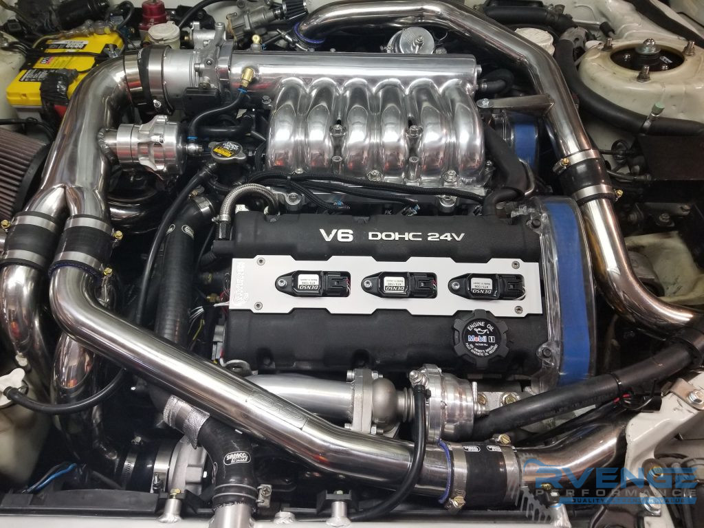
We are excited to announce our coil on plug kit we have developed for the 3000GT and Dodge Stealth Platform. This kit will help take your ignition into the modern era, using easily replaceable parts and eliminating many expensive / hard to get Mitsubishi specific parts.
Features
- Mil-Spec wire, color coded for each cylinder. Long enough to run 3 wires to ECU for sequential fire.
- High quality sealed coil connectors.
- Included ring terminals and heatshrink butt connectors
- New Denso or Delphi “Smart Coils” with integrated ignitors, proven to over 1000AWHP. Modified to fit stock plug wells.
- High Quality Plenum spacer that will not melt (this is needed for rear coils to clear a stock plenum) New, longer allen bolts included.
- New Coil Bolts and Spacers
- This should be run fully sequentially on a standalone ECU or waste spark. Dwell settings are critical if running waste spark or the coils can be overworked.
- Works with stock type/size spark plugs like NGK 4554.
- Eliminates stock coils, stock ptu, and stock type ignition wires. No ignition amplifier is needed for all but the most insane setups. We are currently running 25 PSI on E85 with a .028″ gap with no blow out
Solder vs Crimp Connections
Despite what common sense would say, it is actually preferred to use high quality crimp connectors over solder. Solder creates a brittle spot in the wiring, which is why you will never see it used on professional race harnesses. The other big issue is the stock wire gets very corroded over time and this causes the solder joint to be poor or hard to make. Sanding the wire can remove the corrosion, but its still better to crimp. For this reason this kit contains heatshrink/waterproof butt connectors to make installation easy.
Requirements
We have really tried hard to keep this as a very affordable kit, that will fit the most setups, so you will need a few things depending on your setup and skill level.
It is a good idea to have a simple coil hotwire. This is similar to a fuel pump hotware and will use a relay trigger by the stock coil power feed to take power directly from the battery for maximum coil voltage.
2 Plenum gaskets, one below and one above the plenum spacer.
Some basic electrical ability.
10mm, 12mm, #5 allen key, basic hand tools.
Wire stripper and crimper.
Electrical tape and/or heat shrink tubing.
Installation
We will try to provide easy to follow steps for this installation, but it may vary depending on whether you are running sequential or waste spark and how you wish to run some of the wires. We will be honest and say this is not a paint by numbers or detailed step by step installation, but we will do our best to outline the steps and also answer questions you may have.
This installation will require cutting the engine harness near the ptu and coils because certain connectors are not available to make this plug and play. If you are not okay with this feel free to seek out a different wiring solution, but it may be the only way.
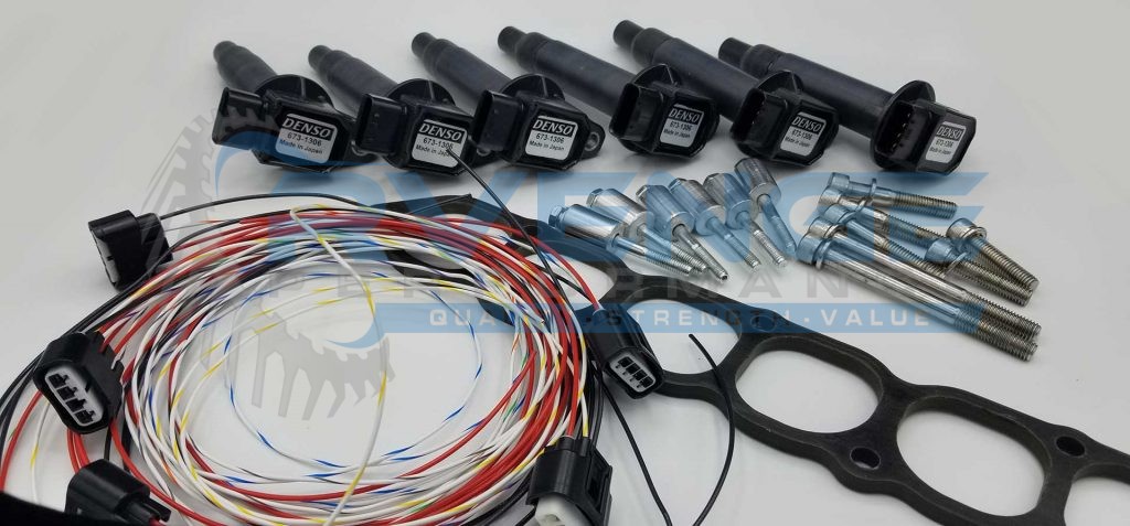
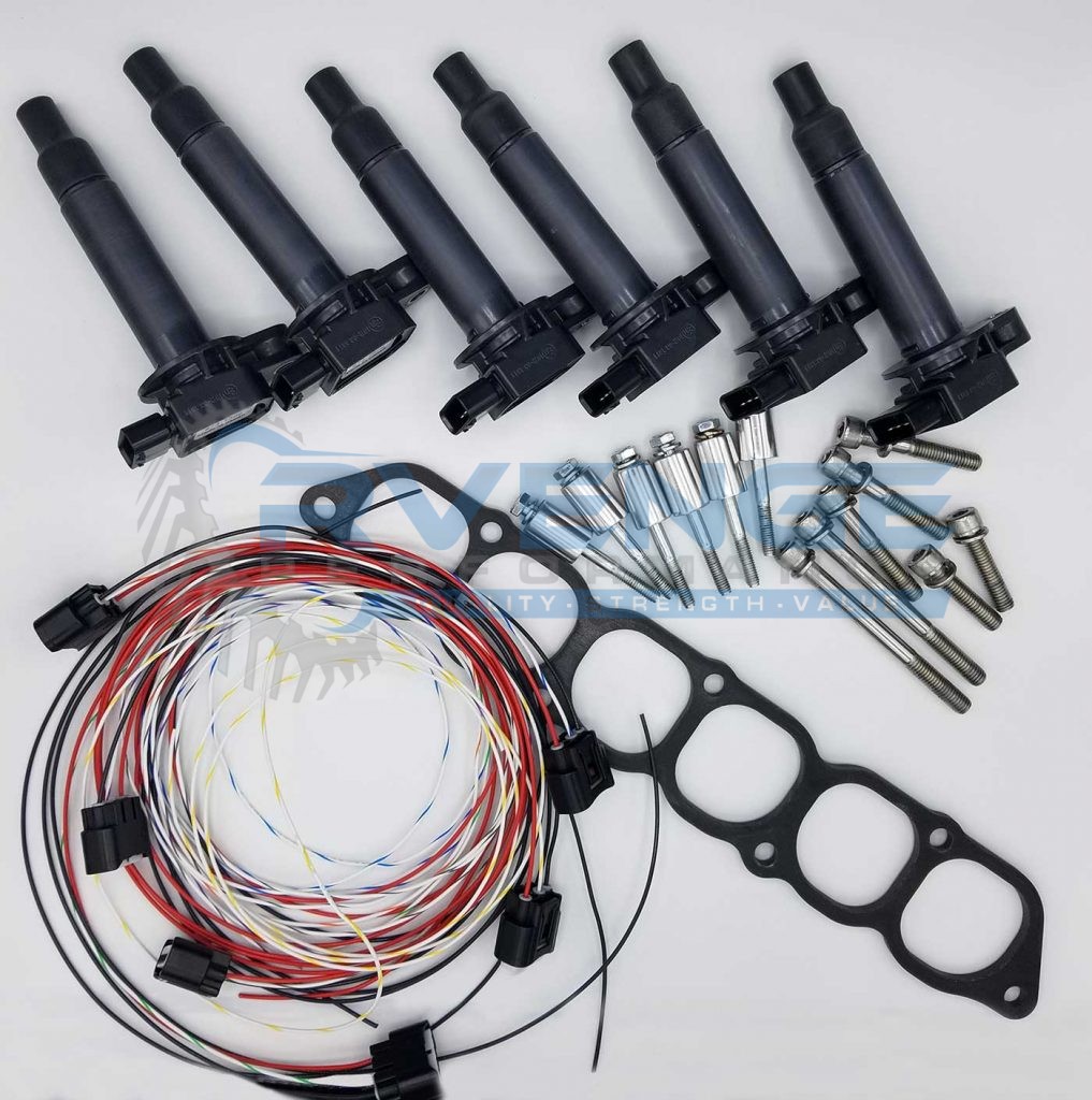
To get started please find a clean and safe work space to layout all your new parts.
- 6 Coils
- 6 Wire harnesses
- Coil Standoff bolts and spacers
- Plenum spacer and bolts
- Crimp and ring connectors
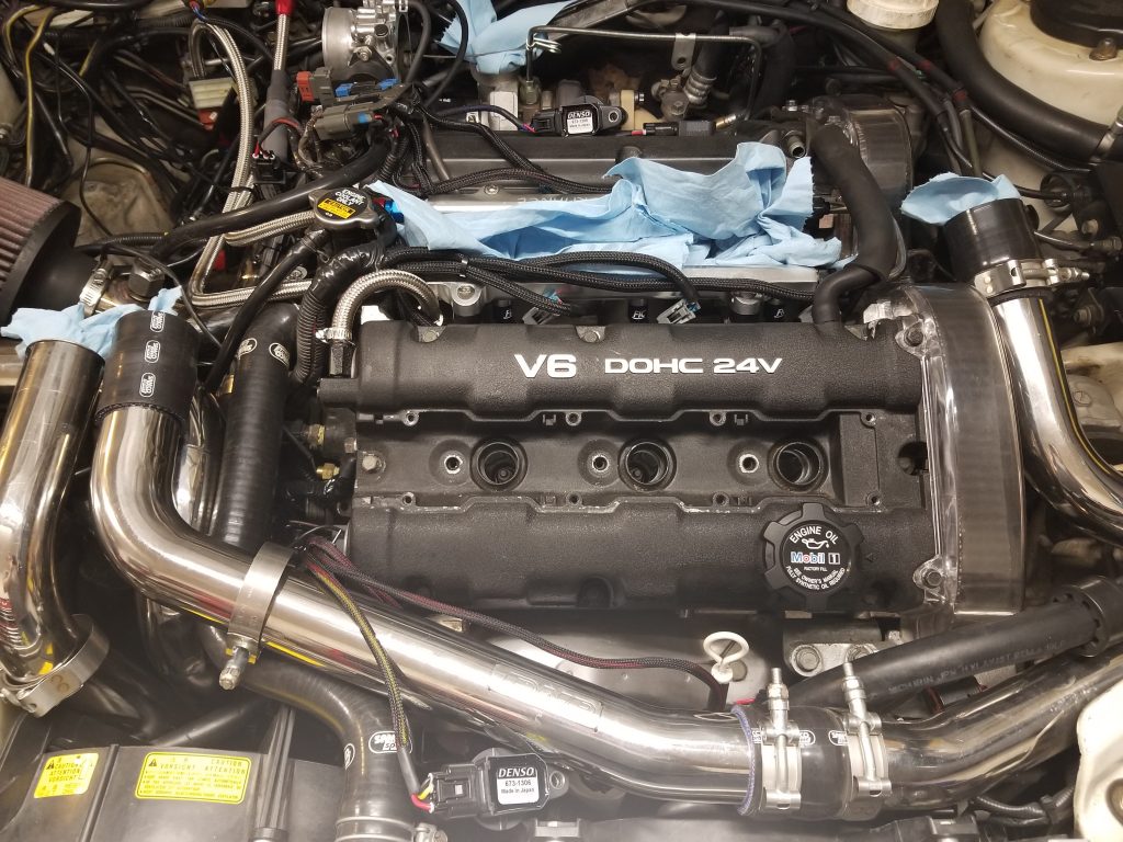
Step #1
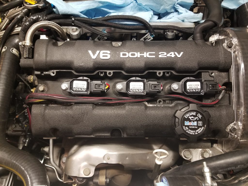
Remove your stock plenum and enough intercooler piping to have room to work. Insert shop towels in any open intercooler piping, turbos, and the six plenum holes. Remove your stock plug wires, coil pack assembly, and ptu. This will vary depending on your setup, but you should be presented with this:
Step #2
You will need to remove the studs on the ends of the lower intake. The easiest way to do this is to simple thread on two of the nuts you had used before and jam them together. Then undo the top nut and the stud should come out. Clean any aluminum burrs or dust that appears.
Step #3
It is a great idea to replace your spark plugs at this time. We recommend either a 7 or 8 series (or colder) NGK copper spark set, depending on your power level. Gap the plugs to .025 to .028 depending on your power levels. We are running .028 on our 550AWHP car.
Step #4
Remove the three center bolts on each valve cover that are next to the spark plug holes. These will be used for the bolts that hold the coils down. They have a 10mm head and should not be very tight. If your valve cover gaskets are leaking its a great time to replace them.
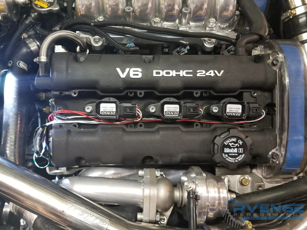
Step #5
Test fit and start installing your coils. The coil will slide down the spark plug hole and click into place. The power plug should face the driver’s side. Place the aluminum bushing under the coil and slide the bolt with lock washer through the coil hole and thread into the valve cover hole. There is a rubber gasket inside, so be careful to get the bolt through it and into threads without cross threading. Lighly torque it down until just past snug for each coil. Your coils are now installed.
Step #6
Begin running your coil harnesses. Each cylinder has a different color signal wire and different lengths. Please use the following colors for the trigger wire as each harness is a different length:
- Cylinder #1 (front near timing belt): White/Purple 28″
- Cylinder #2 (rear near timing belt): White/Gray 40″
- Cylinder #3 (front middle): White/Green: 24″
- Cylinder #4 (rear middle): White/Blue: 72″
- Cylinder #5 (front near transmission): White/Orange 72″
- Cylinder #6 (rear near transmisssion): White/Yellow 72″
You may snap in the connectors, please note they are a very tight fit and can be hard to take back apart, leave enough slack that you can remove the coil for future spark plug changes.
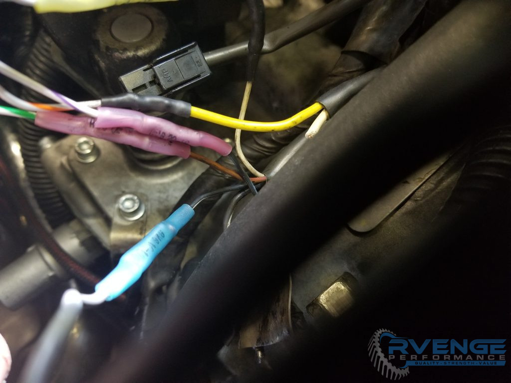
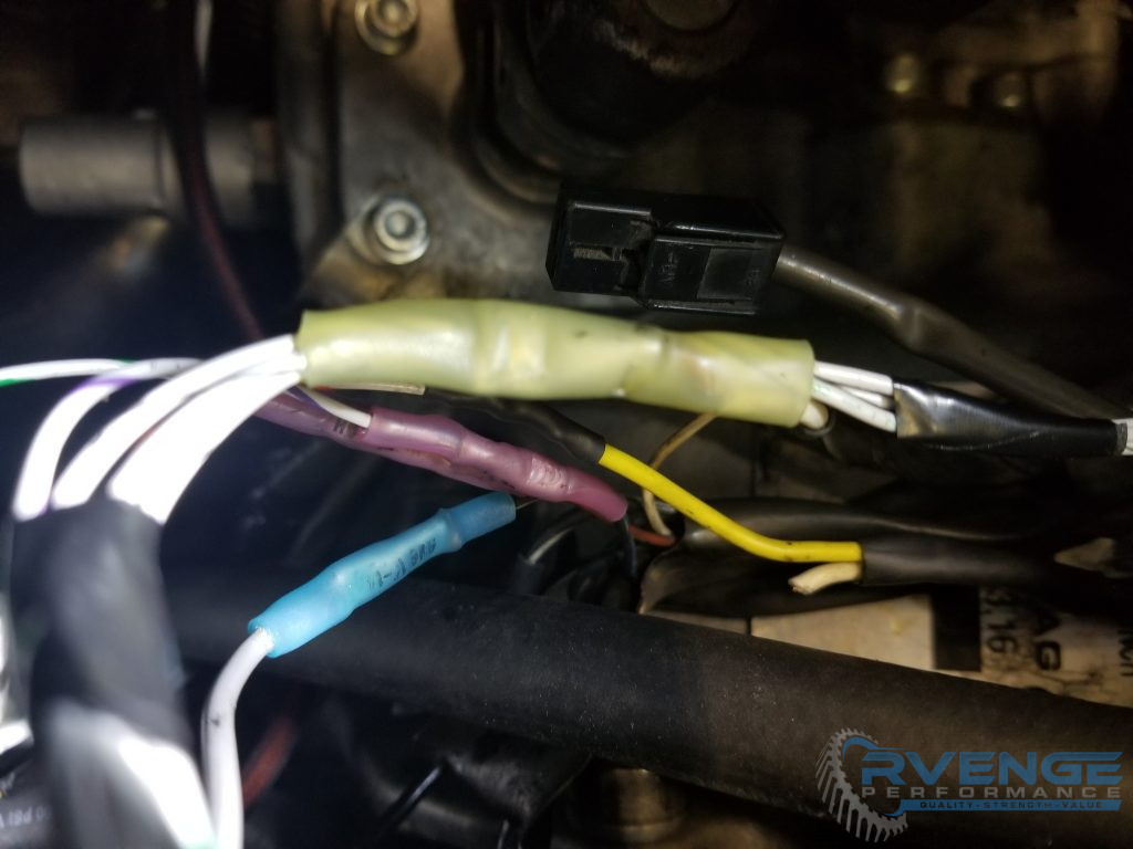
Step #7
Each coil has 4 wires going into it.
- Black – ground. Either ground at the coil harness or to a clean spot on the cylinder head or similar.
- Red – This is 12 volt ignition switched power. Either run this to the stock power wire that used to go to the OEM coil pack set or use a coil hotwire and run it from there. It just needs to be 12 volts that is only on when the key is on.
- White with stripe – This is the ‘trigger’ wire for the coils. These are smart coils with integrated igniters, the ecu need only send a signal to these wires and the coil will fire.
- White with gray stripe (in some instances white with green stripe, 2nd pin from the top of the connector), tachometer reference. 3 are used from one bank for waste spark and 6 for sequential spark.
Decisions
At this point you need to make some decisions. Are you going to run sequential or wasted spark?
Sequential
The coils may last longer when run sequential and you have some more options with aftermarket ecu’s. Dwell is not as critical in sequential either, as the coils will have more time to rest between duty cycles.
If you run sequential you will run cylinder 1,2,3 to the stock trigger wires on the ptu harness. Cylinder 4,5,6 will have to run to your ECU. The provided wire is long enough to accommodate running to the stock ECU location. You will have to locate 3 un-used outputs on your ECU and modified your calibration. We have provided an example for the AEM Series 2 ECU below.
AEM EMS Series 2 Sample Ignition Output Configuration
- Cylinder #4 Pin: 91 (Year 91-93) / 62 (94-97)
- Cylinder #5 Pin:82 (Year 91-93) / 53 (94-97)
- Cylinder #6 Pin: 85 (Year 91-93) / 56 (94-97)
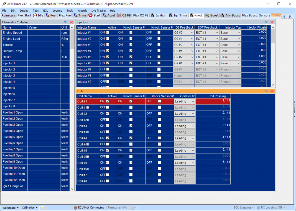
AEM EMS Series 2 Sample Calibration Changes
Below is a screenshot of what is needed to change the AEM ECU to run fully sequential ignition with your smart coils.
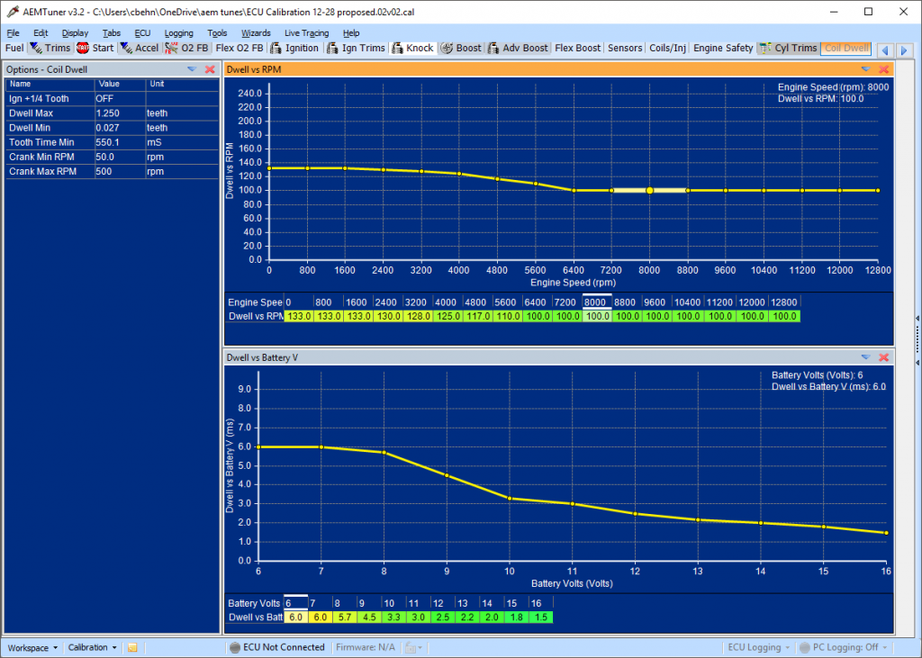
Dwell Settings
Here are sample dwell settings. It is better to run only slightly more dwell than needed as the duty cycle increases with dwell and therefore coil life may be impacted. We have run the below dwell for a season with no issues and it is similar to Denso specifications.
Haltech Example Settings


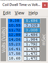
Dwell for Chrome/Flashable ECUs
A good place to start is shown below. The stock dwell settings may overheat the coils and cause a misfire.
Wastespark
With a waste spark configuration you will run the trigger wires in similar pairs as stock.
- Cylinder 1 & 4 will go to 1 & 4 ptu trigger wire
IB1 is black/blue wire - Cylinder 2 & 5 will go to 2 & 5 ptu trigger wire
IB2 black/white wire - Cylinder 3 & 6 will go to 3 & 6 ptu trigger wire
IB3 brown/red wire
*colors *may* vary, verify by comparing to pinout shown on PTU
Dwell Settings for Chrome ECU
Below are some sample dwell settings for Chrome ECU. It is particularly important that you do not run more dwell than needed in a wastespark configuration as the coils will be firing twice as often.
Power and Ground Wire
No matter whether you run sequential or waste spark you need to run all 6 power wires to a switched 12 volt source like the stock coil power wire or your coil hotwire power. You will also need to run all 6 grounds to appropriate grounding connections. How you do this is up to you. We have supplied enough wire you can either just run all 6 sets and join with the feed wire or combine each bank at each head and run a 10 gauge wire from there to the power. As long as each coil gets 12 volts and ground when the ignition is ok it will work. Included ring terminals make it easy to attach the ground to a bolt on the heads.
Plenum Installation
You will need to remove the studs on each side of the lower plenum to use the included longer bolts. Put two m8 nuts on the stud and jam them together, then the studs will be able to be backed out.
You may find that the longer front bolts may get difficult to turn towards the end on your first install. You can tighten and then back out a few times and it should cleanup/cut a few more threads in the lower plenum or you may use a m8 by 1.25 tap. This was done because the next shorter size bolt does not get enough thread engagement and this is critical to ensure you can tighten your plenum over time without stripping the lower bolts.
Testing and finalizing installation
After carefully making and insulating all connections it is time to test your setup. It is not a bad idea to lay all 6 coils up on the top of the lower intake with a spark plug in each and crank the engine over (remove any rags from any open holes and be careful!).
You will then be able to confirm all 6 coils are firing. They will each fire one at a time in sequential mode or 2 at a time in waste spark. If any are not working be sure the plug threads are touching a ground source. If it still doesn’t fire you need to double check your wiring as you will have a dead cylinder after installation.
Once you have confirmed all 6 fire you can re-assemble your car, make any changes to your ecu you haven’t made yet and try a start. The car should run normally and be smooth without any misfire. If you have a misfire locate the problem before a road test. At this point it is good idea to gradually apply more throttle until you are sure you have strong spark and now you are done.
Tachometer Wiring
The latest version of our coil on plug kit for the 3000GT / Stealth platform utilizes the tachometer reference of each smart coil. The tach wire is the 2nd one from the top on the connector and is normally white/gray striped.
Sequential Tach Output
For sequential operation tie all 6 tach reference wires into the stock white tach wire.
Wastespark Configuration
Since each ignition event in a wastespark configuration triggers 2 coils you will want to only wire 3 of the tach reference wires to the stock tach wire. They need to be one from each wastespark pair, 1,3,5 (all three front banks for example).
Coil Cover Notes
To install the front coil cover may require slight pressure downward. This will press against the ears on the coils, which will not hurt anything and over time the coil plastic ears will deflect just slightly and make installation easier. If a custom prefers he could trim the ears.
For the rear plates the ears on the coils need trimmed to clear the plate, there is just not enough room otherwise. We have also heard one report of the rear plate contacting the throttle body and needing the logo section trimmed off, but we aren’t sure what was different about this car.
Success
You may now enjoy your new coil on plug setup! The car should pull strong and have a lot less clutter underhood. You may be able to run a larger spark plug gap than you could before.